01
3+2 positioning
Orient the tool to the feature, then machine with stable 3-axis cutting.
Stable indexed cutting


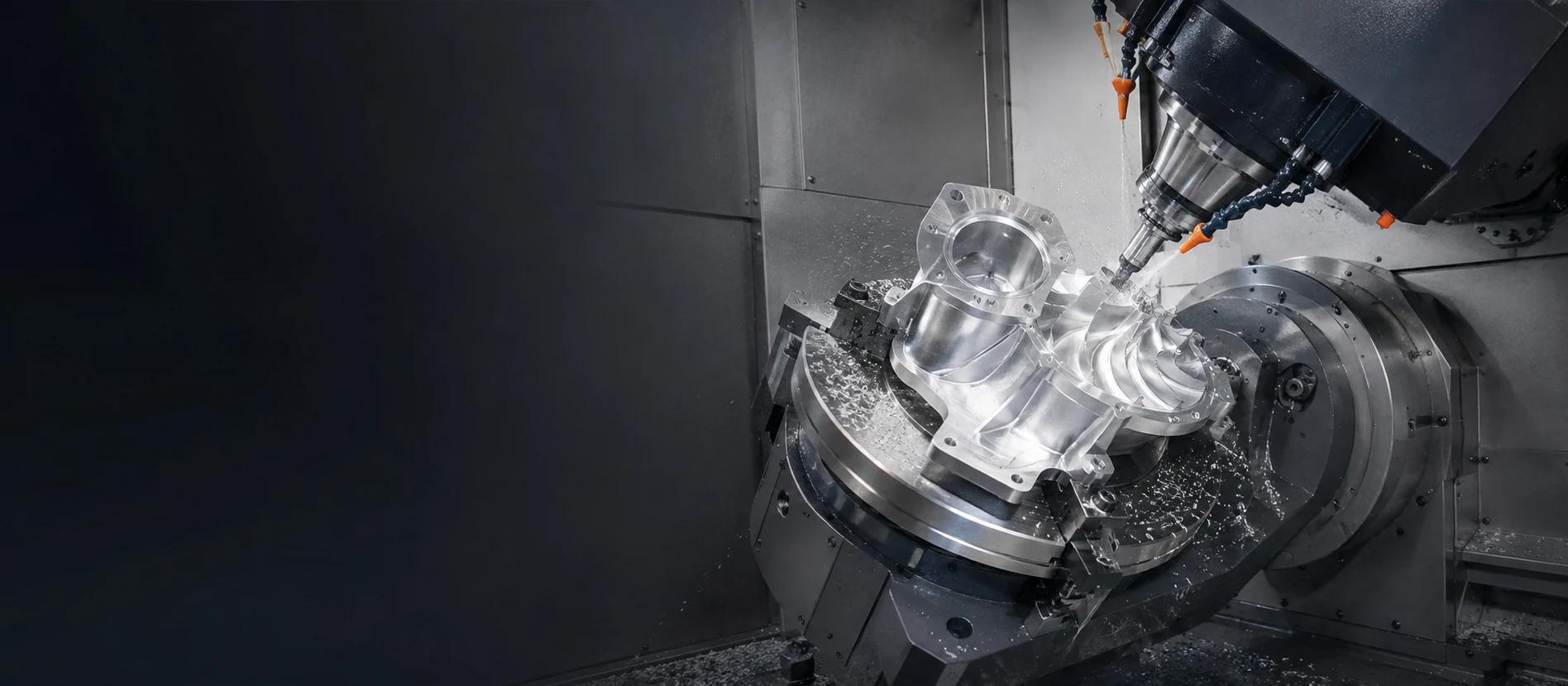
Complex parts, fewer setups, controlled accuracy. JINGLE engineers and machines demanding geometries from prototype through repeat production.
Engineering support for industrial equipment, automation, mobility and complex OEM programs.






A quick capability snapshot for early sourcing decisions. Final values are confirmed against part geometry, material, tooling and inspection requirements.
| Parameter | Website copy |
|---|---|
| Machining Type | 3+2 positioning / simultaneous 5-axis milling |
| Max. Part Size | To be confirmed - reserve equipment envelope |
| Typical Tolerance | To be confirmed - quote-specific tolerance range |
| Surface Finish | To be confirmed - Ra range by material and process |
| Materials | Aluminum, stainless steel, alloy and carbon steel, copper and brass, engineering plastics |
| Inspection | CMM, in-process gauging, first-article and final inspection |
| Production Volume | Prototype, low-volume and batch production |
| Accepted Drawing Formats | STEP, IGES, Parasolid, SolidWorks, PDF drawing and DXF |
01
Orient the tool to the feature, then machine with stable 3-axis cutting.
Stable indexed cutting
02
Keep the tool normal to complex surfaces while the rotary axes move.
Controlled surface contact
03
Reduce re-fixturing, manual alignment and accumulated variation.
Less transfer risk
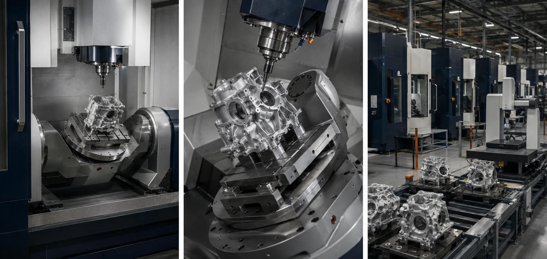
Machine enclosure, rotary table and tool access ready for production.
Complex geometry being cut inside the working envelope.
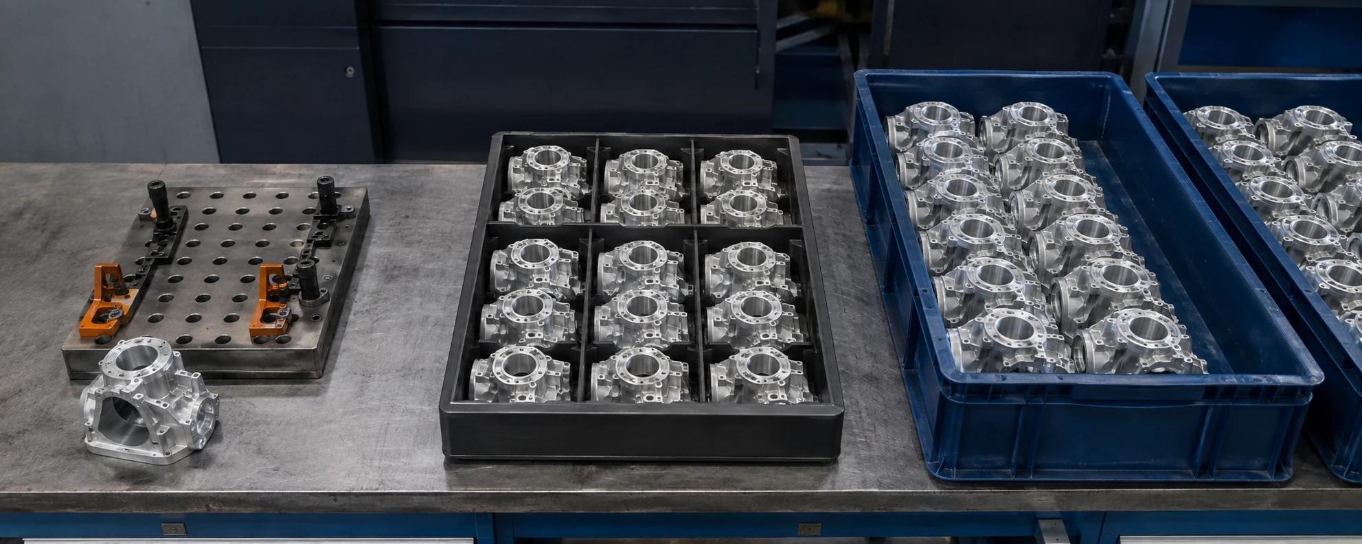
Production floor and controlled handoff to inspection.
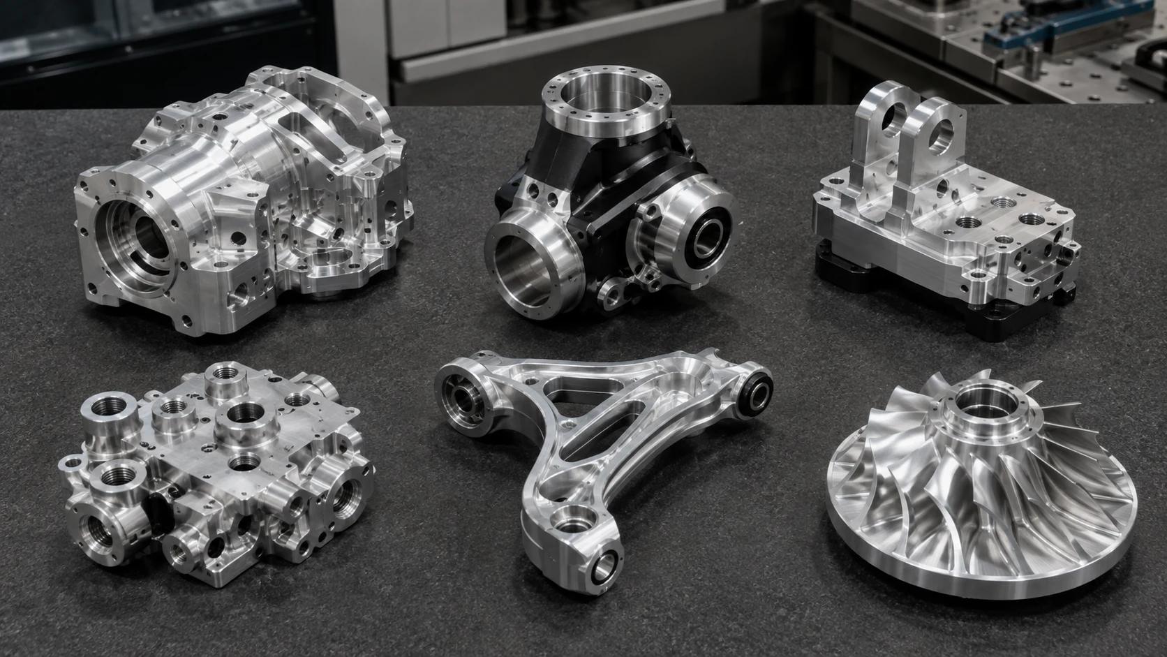
Multi-face housings with interacting bores, surfaces and datum features.
Complex motion components with controlled interfaces.
Multi-directional components for automated equipment and systems.
Fluid-control parts with angled passages and related sealing features.
Production-ready components with complex access requirements.
Application-specific geometry produced from detailed models and drawings.
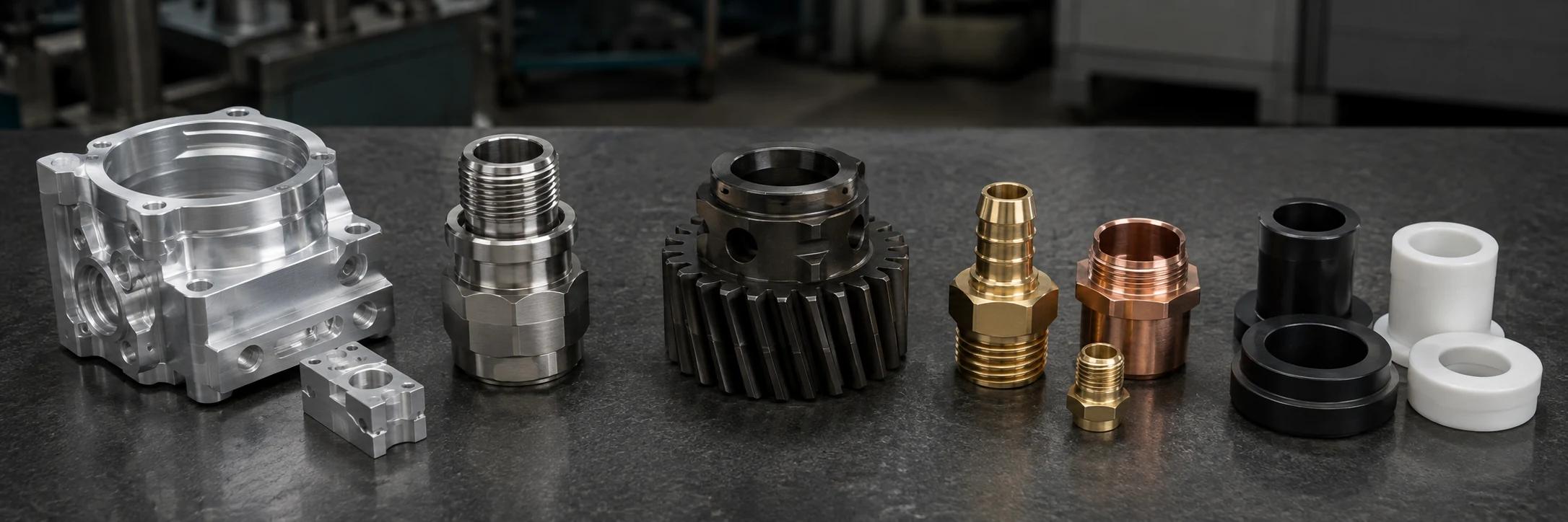
Lightweight housings
Corrosion-resistant parts
High-strength components
Fittings and connectors
Bushings and insulators
Verify material grade, condition and certification before machining.
Check critical features, datums and setup conditions between operations.
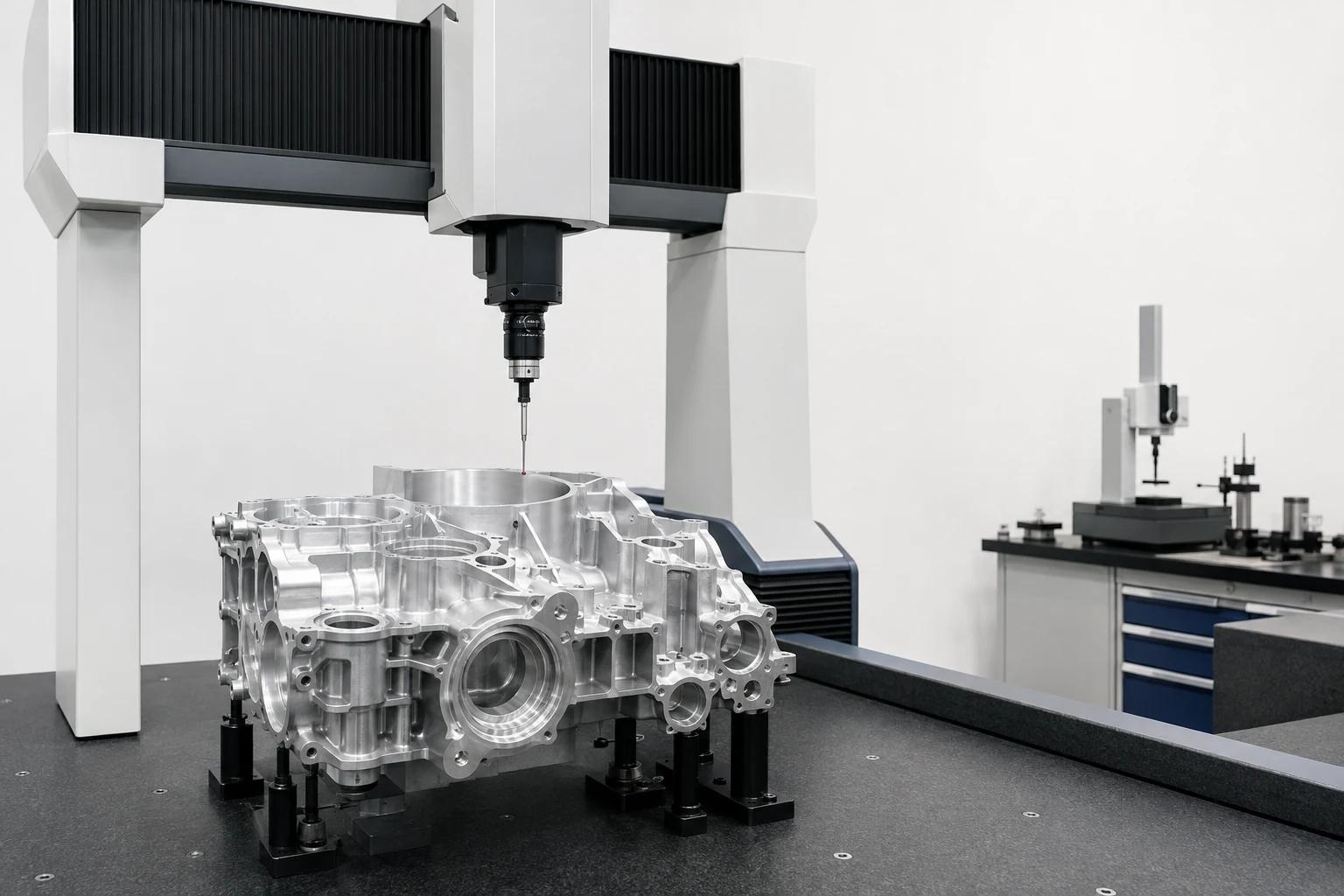
Measure complex feature relationships and provide traceable data when requested.
Confirm dimensional, visual and documentation requirements before release.
01
Validate form, fit and function with a clear DFM review.
02
Build a small, documented run for launch, testing or field trials.
03
Move into scheduled repeat production with inspection and delivery checkpoints.
01
Confirm geometry, access, datum strategy and inspection needs before release.
02
Use indexed and simultaneous motion for demanding multi-directional features.
03
Maintain key process controls as quantity scales from prototypes to repeat batches.
04
Plan probing and CMM checkpoints around functional feature relationships.
05
Receive the certificates and reports specified in the RFQ.
06
Get a clear response path for geometry, quantity and tolerance questions.
Share the model, drawing and critical callouts. We will confirm the practical tolerance range against geometry, material, setup and inspection requirements.
We machine aluminum, stainless steel, alloy and carbon steel, copper and brass, and engineering plastics.
Yes. Send the model, drawing, material and quantity so we can plan the appropriate production route.
Yes. Send the STEP model with the current drawing so critical dimensions, tolerances and inspection requirements are clear.
Yes. CMM reports and other agreed quality documents are available when requested in the RFQ.
Send the model, drawing, material and quantity. We will review the requirement and confirm a practical quote path.
Send the information you already have. We will review the geometry, clarify the open points and return a practical path to quote.
Related machining processes